
For one of my newest projects I will need a bigger PMT than the Valvo XP2011 tubes that I have. The needed diameter is 3 inches because we will be dealing with a 3″ by 8″ Nai(Tl) scintillation crystal. Yeah this is the biggest one I have ever found and I had to get it. But I have to disappoint you – this article is only about the PMT.
In general a good new XP3312 can be around 250-300 Euros but you can often get them cheaper from smaller medical device supplies wo take apart old machines.
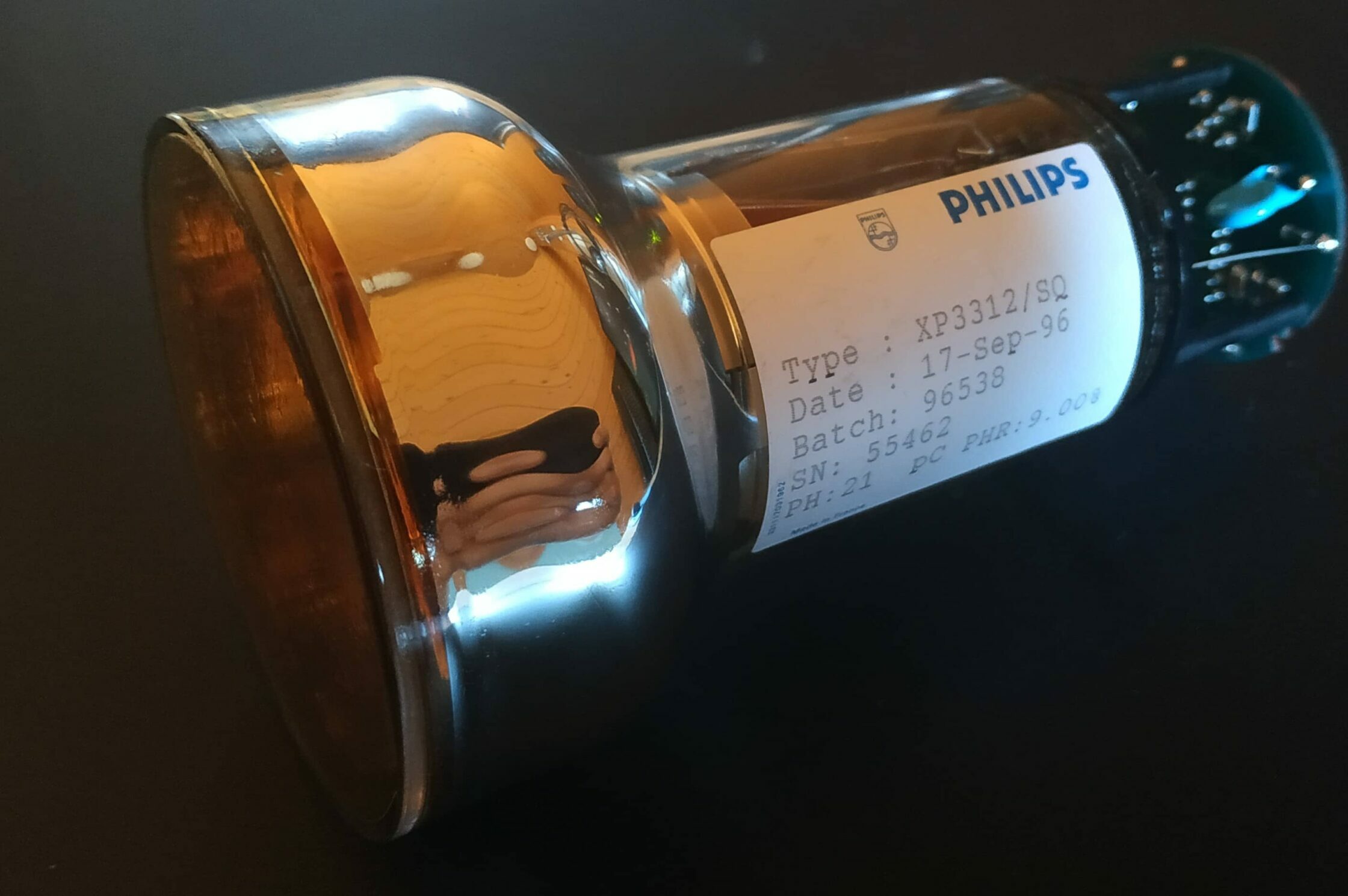
Like already said, the XP3312 is suitable to deal with 3″ scintillators. It has only 8 dynodes which make it not too much of a high gain PMT. But it was made to work with NaI(Tl) scintillators in Philips gamma cameras in the first place so that should not be a problem.
It is often compared to the more modern XP5312 which in my understanding is way superior because of the 9 dynodes, a higher gain and a smaller dynode configuration which makes it less prone to magnetical interference. I believe that combining a XP3312 with an old soviet made plastic scintillator often found will not give any usable pulses because the gain is way too low. Even the XP2011 with 10 dynodes struggle with those and need a voltage of 1150V to start detecting pulses of higher than 40mV.
Here are some important specifications from the Photonis Catalog (year unknown):
– Gain @1000v: 2,4×10^5
– Supply Voltage: 800V – 1200V (max), typ 1000V
– PHR 7%
– Socket FE1014
Voltage divider:
K (2R) D1 (1,5R) D2 (1,5R) D3 (1,5R) D4 (1R) D5 (1R) D6 (1R) D7 (1R) D8 (1R) A
R = your Resistor value e.g. 10M Ohms multiplied by the factor above will give you the resistor value you have to use. If you choose 10M Ohms as your R, you have to put 20M between K and D1, between D1 and D2 … 15M Ohm between D2 and D3 … 10M Ohm between D4 and D5 and so on.
The tube does NOT have a voltage divider on the pcb that is soldered onto the tube pins. I have not yet figured out what it is but that seems to be only the last part of a negative HV divider network where the signal is fed out. the resistor network is supposed to go onto the dupont pins. When dealing with positive HV I recommend cleaning the whole PCB and rebuilding it with the resistor network on it.

