
For plastic scintillators or scintillation crystals
Recently I have bought a Ludlum Model 3 survey meter which supports geiger müller tubes and also scintillation probes. Since the one I bought only came with a Ludlum 44-7 pancake geiger müller probe, I could either buy one or build one by myself. Actually the original Ludlum scintillation detectors like 44-17 or 43-4 seem pretty expensive to me, since I had a bunch of photomultiplier tubes and scintillators laying around.
Another purpose for the scintillation probe will be my gamma spectroscopy unit which I am also currently building.
The Theory
A (gamma) scintillation material emits light when it is hit by a gamma quantum. That is the simple version of a much more complex procedure that takes place in a scintillator.
The light coming from the scintillator must be lead to the photocathode of a photomultiplier as effective as possible. Therefore the scintillator is coupled to the pmt with a silicone grease. Some manufacturers use ducting silicone that hardens but I really don’t recommend doing that because you won’t ever get it apart again. The sides and the back of the scintillator are wrapped in PTFE due to its high reflectiveness. That must not be done to encapsulated crystals.
When the light hits the photocathode of the pmt, it is converted into electrons by the photoeffect (what Einstein discovered and got the Nobel Price for). Inside the pmt the electrons go through the vacuum to the first dynode. There the electrons free some of the electrons on its surface. Those electrons will travel with the electrons from the beginning. The same procedure also happens at all other dynodes and at the end there is a high enough ammount of electrons to make a detectable electrical impulse coming from the anode.
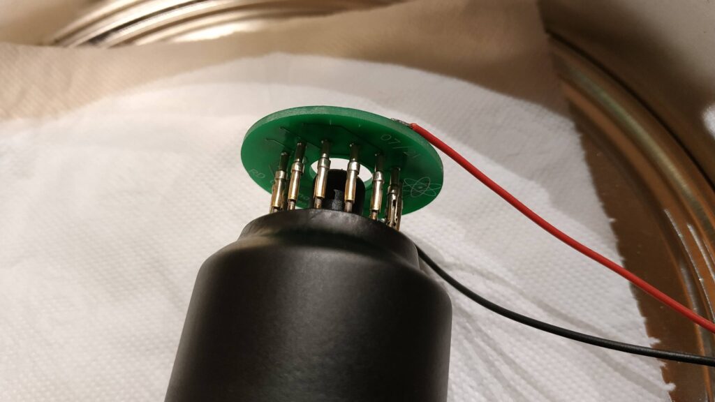
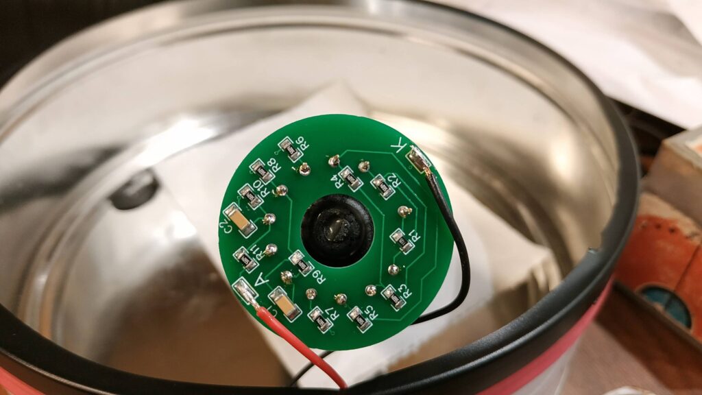
Electrical build

I have made a PCB for the voltage divider with capacitors to make the build more convenient. You can also solder the voltage divider directly to the tubes pins. Be careful not to overheat them because the glass could crack due to the mechanical stress from the expanding pin.
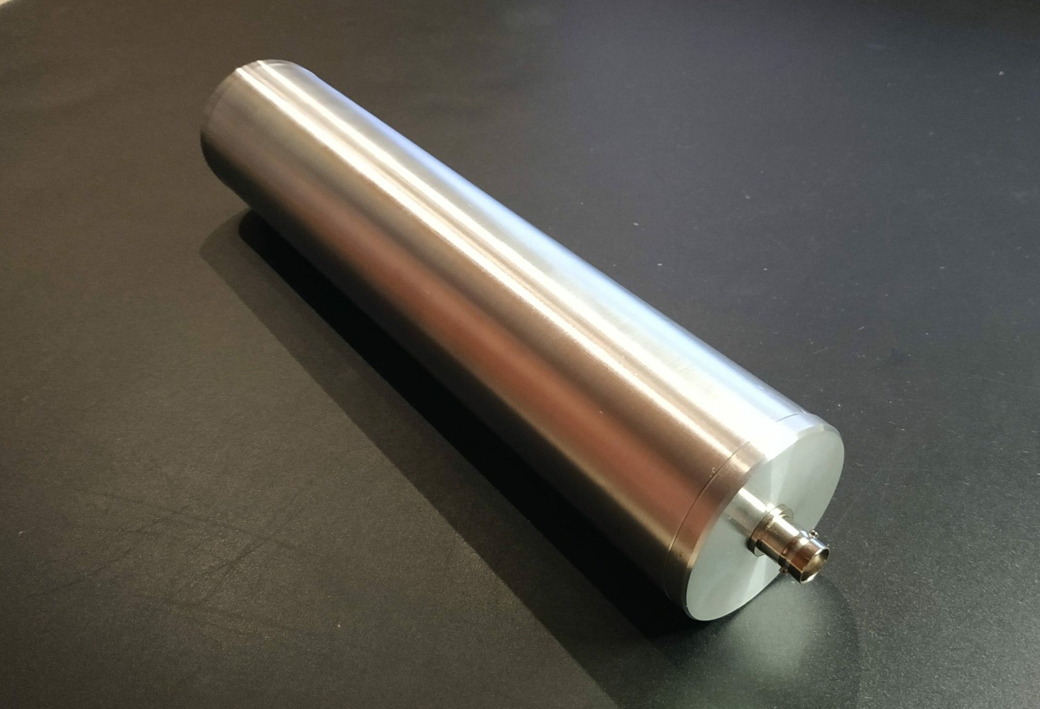
Making a Case
I wanted to make the case as rugged as possible but not use anything magnetic. Linear PMTs don’t like magnetic fields because they interfere with the path that the electrons travel inside the vacuum.
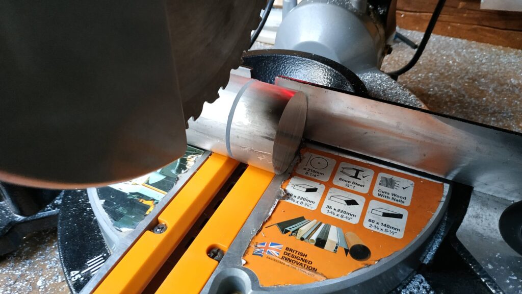
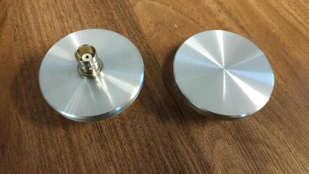
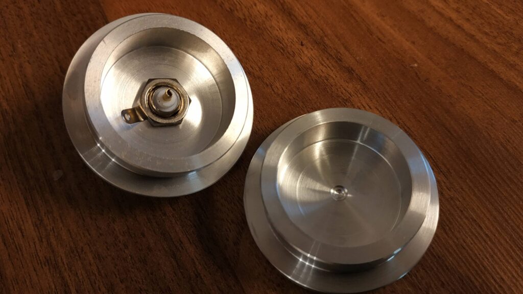
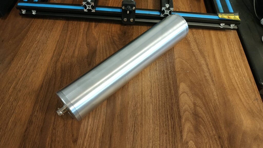
After all I am pretty satisfied with the way everything turned out. It took me almost 7 hours to that point because there were changes to the plan to be made. Sadly I can not describe every step to make the aluminium housing because everyone wo uses a lathe will do it in a different way. What matters is the result.
This is a work in progress, I will post more details soon…
Update:
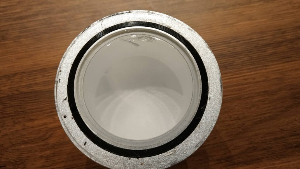
To make sure the end caps are 100% light tight you should apply a seal between the two metal surfaces. I used my laser engraver to cut a round seal from a sticky textured vinyl sheet. Also the wires should be shorter than shown in the video to minimize any failures because of the high voltage.
Please never use negative HV on the probe because the case is on GND potential!
