
Recently someone asked if it was possible to build a cheap GM-Driver circuit which is a HV source and a pulse output connected to a speaker. When a gamma/beta/x-ray is detected by the tube, the unit will make a click noise.
I’ve decided to make one only by using very standard parts everyone should be able to obtain. To be honestly, I have already built one of those some years ago but have not really documented it properly. The unit still works fine with all the parts shown below.

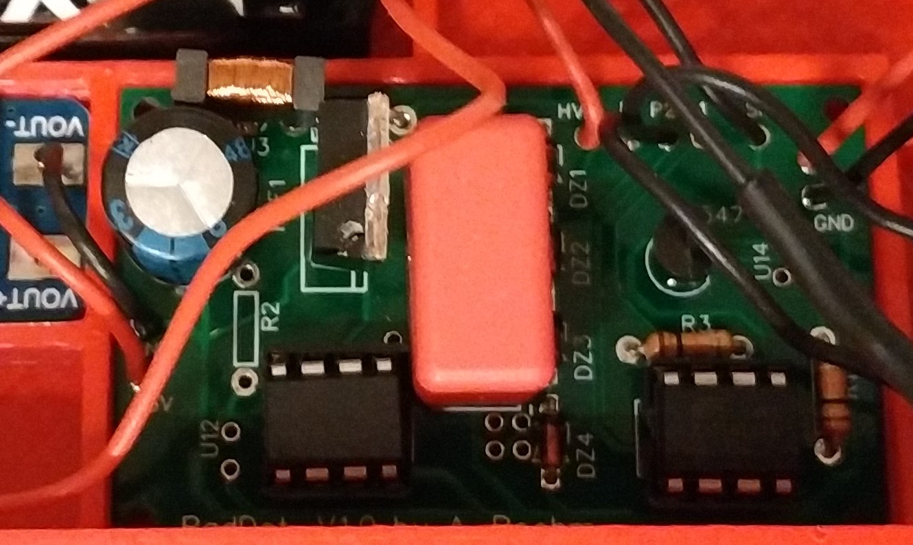
When the MOSFET Q1 shuts the current through L1 off, a current pulse rushes through D1 which is a standard 1000V rectifier diode. The current charges C2, a high voltage rated 100nF foil capacitor. When the set voltage is reached the Z-diodes regulate it to their limit. The voltage can be lowered by just shorting one or multiple Z-diodes out. In the given case, the voltage will stay at 400V. The diodes should be chosen with a reverse saturation current as low as possible to lower the idle power consumption to a minimum. The current to charge the GM-Tube MUST be limited by a 7-15M resistor R1. When a ionization is detected the GM Tube discharges through R2 into the base of a BC547B NPN transistor. The transistor lets current flow and pulls the pulse output low for a very short time. It is important NOT to use a FET as Q2 as it will be easily be destroyed when the HV builds up at the gate.
The PWM drive for Q1 and the pulse-out-detector which drives an active buzzer can be both made by using a 555 type timer IC.
Coming soon: Schematic for GM Driver with 555 timer ICs and Schematic for GM Driver just using one AtTiny microcontroller. Edit: March 24 2022, I have had many other projects since and have not forgotten about this one, there will be an update. Also check out my other projects.
This is a work in progress…