
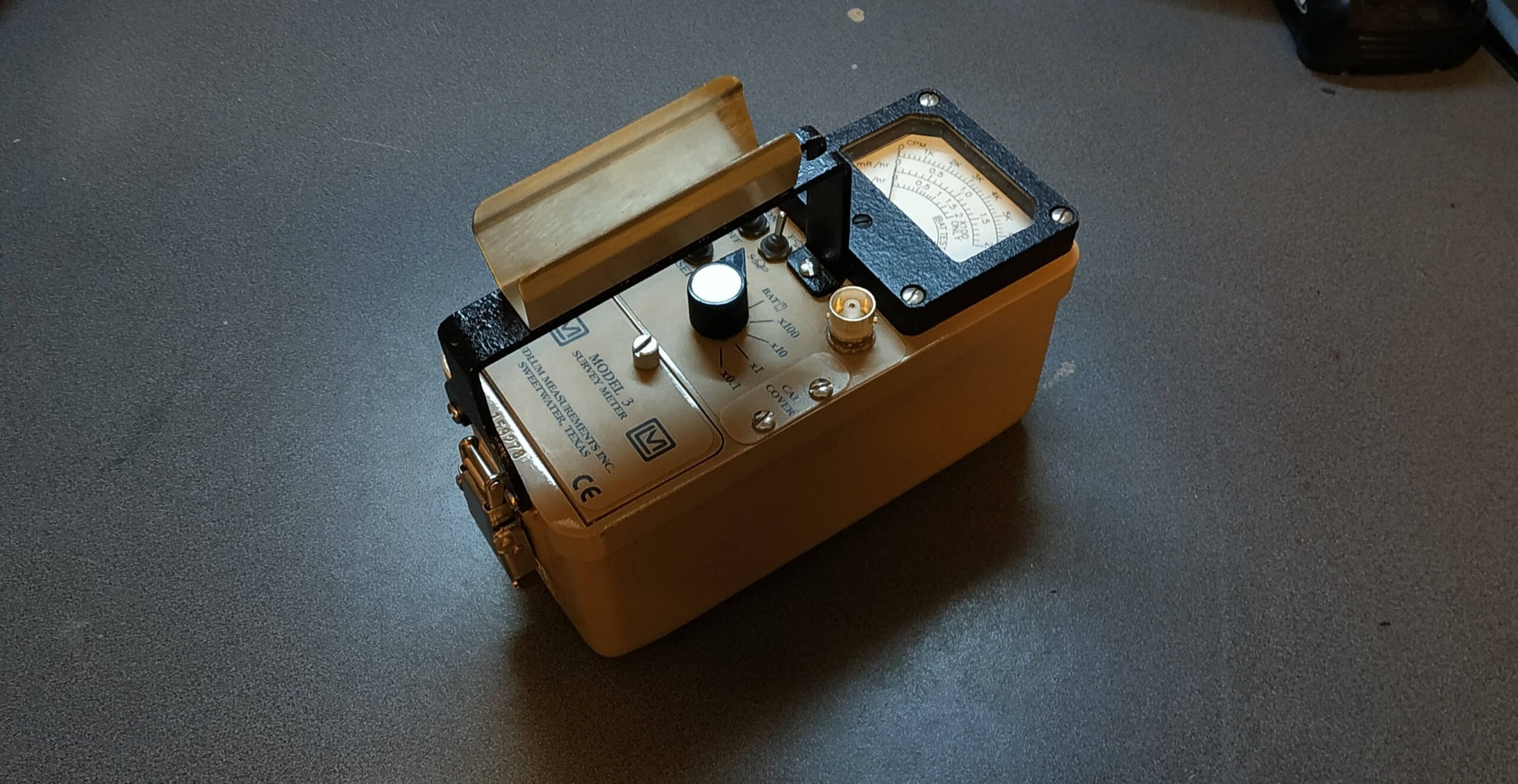
Recently I have bought a Ludlum Model 3 because I wanted a professional meter that can drive scintillation probes as well as geiger müller tubes. In this article I take a look at the functions and the build of the meter overall.
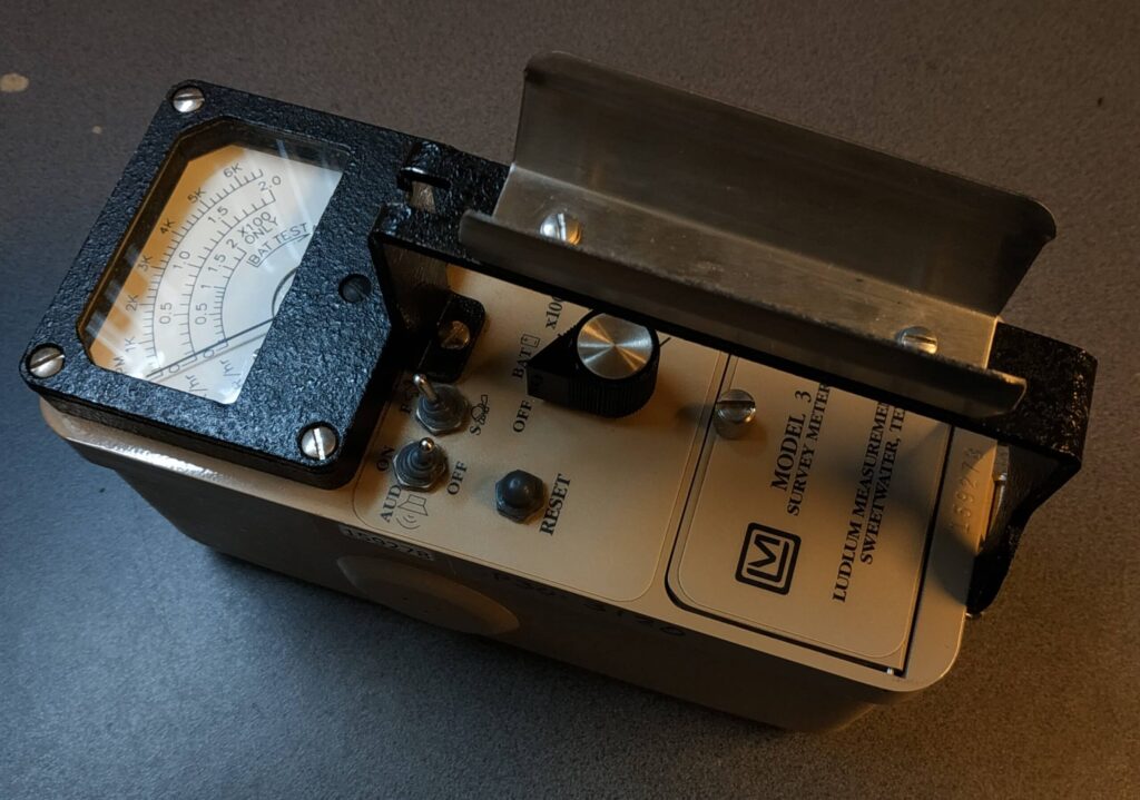
There are various switches and a pushbutton on the device. The central rotary switch turns the device on like a common multimeter and sets the desired mode. The device has 5 modes. These are: OFF, battery test, 100x, 10x, 1x, 0.1x.
The last four are the scaling options of the display. The displayed value in counts per minute is multiplied by the set scaling value to obtain the measured value.
The device has a fast (hare) and a slow (turtle) measurement method. In the respective measuring method, the pointer moves slowly or quickly depending on the set method. Accordingly, one can quickly detect changes (hare) or measure precisely (turtle). The mode is set by the inner of the two switches on the top left of the control panel. To reset the display value to zero, the reset button below is pressed briefly.

To the left of the measurement mode selector is the audio switch, which turns the rather loud piezo transducer on or off. This produces the characteristic Geiger counter click in the ON position.
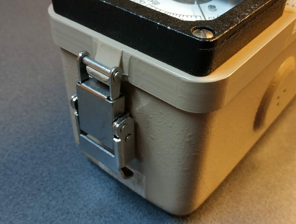
Let’s take the device apart. The first thing to notice is the extremely solid construction of the unit. The upper part of the meter is made of thick cast aluminum, the handle is made of 3mm steel, the display is protected by tempered glass which is enclosed in a steel frame. Even the rotary switch is made of aluminum. When looking for plastic, you will only find it in the battery compartment.
The device is opened by stainless steel tabs at the top and bottom of the case. Then the upper part made of cast aluminum is pulled out and placed next to the lower tray.
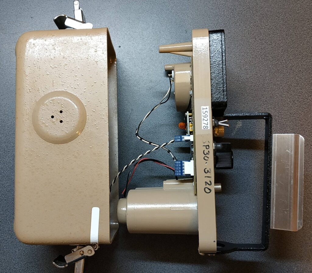
On the bottom of the control panel is the battery compartment and the circuit board. A double wire connects the circuit board to the piezo transducer in the side of the housing. It is noticeable here that a PCB without solder resist was used. There is even an apparently subsequently soldered wire visible at the top right of the diode near the IC, which connects the anode of the diode with the shield of the high voltage section. The shield is simply a piece of PCB.

The entire schematic can be found in the manual of the meter. The entire layout is kept very simple with no unnecessary features. At the bottom of the case, a packet of desiccant is usually added to prevent corrosion from trapped moisture.
